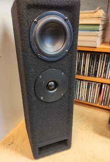
PMC LB1 a historic investigation in legacy sound, part 1

 Part1

Today some vintage PMC LB1 studiomonitors did arrive at my desk.

For those unknown: just follow the link for a description of these UK manufactured benchmark loudspeakers, developed by some former BBC employees.

They came accompanied with a assorted collection of 'spare' tweeters and woofers.


Upon first test nothing worked as it should: we quickly found that both 1 and 2 +/- connection of the speakons where paralleled. Now that is a bit unusual, as in pro-audio we use a NL4 speakon to feed a loudspeaker with a high/low split signal. Nowadays the majority of prof. amps have 2 channels feeding 1 speakon. So the box effectively shorts the 2 channels. Not good. Oh well..easily sorted.


Still not very good sound. So let's open it up: and behold and wonder some fire has been inside.

Now this really made me curious. I know the loudspeakers have been driven with Bryston 4B amps. (Not to shabby!) So underpowered clipping amp couldn't be the reason.

So let's investigate...


First thing I did was try to find a schematic for this cross-over online. No luck.  So I drew it up myself:

Now to get an idea of the design philosophy we examine the values of the components closely. Immediately the doubling of C1 vs C2 (6.8uF) springs out, which will point to a textbook LinkwitzRiley 24 dB filter. In those days modelling software (like LinearX Leap) was available but apparently not wide spread. (I did acquire my copy somewhere in 1996). So we could investigate this pointer further. I de-soldered the 2 coils and measured them. Not very accurate, but both values and even more their ratio (1:4.5) prove this indeed it is a textbook LR filter.

To determine for what crossover frequency they designed that filter we have to do a bit of guess work. because you will have to know the impedance with which this filter is terminated. What if they just took the (DC !) 6 ohm resistance that is mentioned on the tweeter ? (of course this is not correct but read on..) In that case the crossover will work as a (electrically!) perfect 24dB LR crossover at 2100 Hz.

Anybody who has dabbled a bit in passive crossover design knows the horrors: components all interact with each other, are never ideal (parasitic inductance / capacitance)  and the terminating impedance is never a constant (ohmic) resistance. So yes, changing f.e. capacitors with different brands (with the SAME value, duh) will have an impact on the sonic behavior of a filter. But that is a different story.

First let's measure the tweeters to see if that terminating resistance indeed is more or less a constant 6 ohms..


And yes: the green line is an impedance measurement of the raw driver. That is rather flat to begin with so one immediately thinks: ferrofluid . Indeed in the '90's that was considered quite the bomb. Some manufacturers did use ferrofluid in everything (even 15" speakers, bad idea!)

One of the 'spare' tweeters had some note saying "possibly faulty", so I opened it up to find out. 

Now opening up drivers and in general reconing or refitting new membranes is NOT a good idea (with nowadays manufacturing tolerances) but that is an other rant, this tweeter was 'possibly' faulty anyway:

Yes, JL (in 2015) this tweeter is definitely faulty..I might even say totally foobarred.. But also filled with (a bit dried) ferrofluid so: confirmed!

Now what type/brand tweeter would this be, because they look awfully familiar?

And, suprise, suprise: when I pulled away some PMC branding sticker I found the original VIFA D27TG35 sticker. Take note of that exact number because this is remarkable!: In that same era (somewhere in the '90's) I did design and manufacture  a small multipurpose loudspeaker (build maybe a 100 units or so) with that exact same tweeter. When they went out of production I bought the remaining stock and that was the end of that build. (fairly recently I did a restoration of one of the installs-->)


And no, some Peerless or (Vifa rebranded) tweeter with a similar number will not be a replacement! But you can have your own opinion: nobody will get hurt..

Onwards with the filter, cause still some components need to be explained: more precisely the burned resistor(s). First one is a series resistor with a paralleled capacitor. This will serve as a attenuator for the tweeter and also as a slight top boost (ferrofluid, y'ken) with +3dB point at 9khz. Fair enough. But it will make the filter 'see' a higher load.

But what's that 100nF (with series 8 ohm) doing there? Those values make no sense at all, it does precisely nothing in the audible band. Also as an zobel network (to stabilize amp load) it is nonsense in that position..oh well.. brainfart from the designer??

So this leaves us the one resister that is paralleled with the combined load of tweeter and attenuator to get back to the correct load for the LR filter. From a designers perspective this is an awful solution: that resistor will get hammered with a lot of power, so no wonder it is burned. 

Previous repairs show a (also way to small) installed 13 ohm resistor. Now that's an odd value. Not likely in my opinion. 

Back to the measurement above: if I insert a 10 ohm resistor and re-measured the tweeter with attenuator I got that yellowish line: an almost flat, straight out 6 ohms, which brings us back to the desired, flat line 6ohm for our LR network topology...

Now hows that for loudspeaker forensics?


..on to Part 2


PMC LB1 a historic investigation in legacy sound, part 2

 Part 2

 ..on wards..

So now what will we do? Upgrade that filter with audiophile components?  Redesign it with what we know now? Or even use some DSP to make an active system?

NON of the above.

Audio reproduction is a construct so if we want to know why that box was so successful in those days we have to thread really careful!


So what I did was replacing those burned resistors with beefier ones of the original value. However, I did get rid of that mystery non working 100nF to make some room. Purists forgive me if you hear a change in the 200kHz region.

I also replaced that electrolytic cap with some MKT  I had lying around. We all agree that (old) electrolytics are a pain, right?

They serve as impedance-equalizing for the woofer so not in the 'signal path' anyway.

So how does it sound?

At first I was a bit underwhelmed, so let's look at the measurement to see if I perhaps made a mistake by swapping polarity of one of the components . (note to self, why don't you ever mark down how things where connected?)

No, totally correct. As expected: perfect all-pass behavior. Also the inverted tweeter experiment gives a deep null.

It does sound that way too, like a well balanced loudspeaker. Albeit it bit dull and boring perhaps to much zero-phase-fir-filtering for me lately?

puzzled...


..So let's turn it up and see what happens...

AHA !! Euphonics !! I can do euphonics, after all I have been a live sound engineer for many years. So I need a bigger amp, as I was testing with one of my whimsy yet brilliant sounding gain-clone-single-chip amps. 

Unfortunately I don't have some spare Bryston lying around but I do have some class A amp from a prior experiment.

Now stuff starts to be clear why people have blown these speakers into smithereens: they just say more more more more more..

More off what? More of that fantastic low-end! That tweeter I do know: not the best 7kHz I ever did hear, but that transmission line is real fun!

Here you go: measurement very close to the port. You can see the smoothly playing 60Hz (such nice frequency)

But it does look a bit worrisome around 220Hz, right? That's a general problem with transmission lines, maybe I can repair that a bit with some more experimental stuffing

Now will this loudspeaker work as a generic monitor loudspeaker in 2023 ?

We would first have to define what a monitor speaker is. 

Contrary to some big names in loudspeaker-design-industry (not studio people), I have the feeling that working as a mixing engineer is also a part of the creational phase. Not re-production as in playing back the end result.

So a studio monitor is not there as a reference of the end result but to make you do your creative part in a stimulating way. And press you to reach further, higher, better, newer.

These monitors came into fashion when we (in live sound) started working with band pass (6th order) subs..and hey: let's try some Portishead / Massive attack and drum 'n bass (Propellerheads!)

...woohaaaaa... this is the shit..damn!

How revealing is that!

Now does recent music like Billie Eilish, Whispering Sons, (modern) classical music work? nah, unless you really enjoy that '90's sauce on everything.


That being said: some of these sound system blokes are experiment a lot with 1/4 wave sub, as if it is something new.. So who knows what will come into fashion again, after all everything seems to go in circles.


And another day of listening + experimenting: Red line is port measurement without any additional stuffing, whitish line is with some extra 'sheep wool' stuffing. Sure: low end is cleaner + sounds more tight with the stuffing but the 'fun' is gone.. 


More research is required: I will use the extra parts to make a home brew TL and in the meantime get a better (DSP) crossover because the groupdelay of that conventional filter is starting to annoy me. The restored boxes will serve as a reference (in my memory database) to that.

Keep checking!

PMC LB1 a historic investigation in legacy sound, part 3

 Part3


As I mentioned in the previous post: I was getting annoyed by the overall group delay as it is introduced by the text book IIR (LR 24dB/oct) filtering.

So here's the experiment: home brew TL with a very cheap 4" speaker. I totally forgot to take pictures of the making, not that interesting at all: it is a standard 1/4 lambda backloaded TL with some folding. 

Very similar to the PMC design

The big difference will be the filtering: I used one off my DSP boards to make a overall zero phase shift X-over using FIR filtering. How to do so will be a topic for a different series of post. Soon. Maybe.


While presenting them to my audio peers it became clear to us that there's no way back to IIR filtering once you have tasted the reverberant field as it is presented by a zero phase system..

But that wasn't the topic of this experiment. We where investigating the sonic properties of a Transmission Line. Funny coincidence: right at this moment the Amsterdam Dance Event is happening and all newspapers are full with interviews with the current stars of EDM. Accompanied illustrations show pictures of studios with big (PMC) transmission line monitors. 

So this is hot stuff at the moment.


 Now how does a TL sonically compare to a different approach?


Very same speaker, different hornloaded tweeter but we can ignore that. Literally. We have been practising listening for some time.

In this small cabinet I used a digital implementation of the Linkwitz Transform to get some LF response squized out of that wee speaker.

In the STM32 part of this blog I did talk a bit about the intricacies of this.

So we now have two things to compare AFTER each other. As always when listening and evaluating audio stuff: you have to remember it for a few seconds. Which isn't simple and definitely needs some training..


How do they compare?


Purple line is close to the port of the TL (transmission line) while the green line is close to the speaker of the LT (linkwitz transform) closed box.

Clearly the TL has quite some lower response around 60 hz (again, such nice frequency) all though at the cost of a bit funky phase response.

Forget the resonances at 180, 300 (hey..odd harmonics..hmmm) they certainly spoil the fun in this experiment and are the main reason that some music really shines while other sounds horrific. Missing fundamental psycho-acoustics at play here.

But we are not finished yet.


I totally like that 60hz. From such a small box. So I made another, bit bigger TL with a 10" speaker. Right at this moment it is playing at my feet under my desk. Also at actual quiet levels it really does bring an extra dimension to the genre I am currently digging in:

Hauntology 

(EDM is too boring for me)

So you can get an idea of the sonic landscape.


Now what about those pipe harmonics in this setup?

Well, very steep FIR filtering at 80 Hz proved to solve that.

How? By using down sampling to a sample frequency that doesn't take zillions of coefficients to get the desired resolution of the linear phase filter.

Naturally (a lot of) delay has to be added to the (high end) desktop speakers. 


And now things get really interesting: 

I never was a fan of 'separate' sub woofers. Also in live sound. The setting of delays from subs to mains or vice versa always is giving you grief when they are some distance apart. Most certainly if you understand what phase-alignment involves.

Why would that be as wave lengths around those frequencies are in meters? So how could some centimeters make a difference? Well maybe the (much higher in frequency) harmonic distortion produced by subs have to be in time with your main?

With the above very steep filtering I could, at least at lower levels, get rid of that distortion and now the sub is behaving as it should: it seems as if my wee desktop speakers are producing a tremendous amount of accurate bass. Most certainly with instruments I know well (like bass guitar)

I also tried a similar setup with a conventional cabinet, but that doesn't give you the same results: a TL has a lot more efficiency at the freq. of interest, meaning the cone has to move less and thus produces less distortion compared to an (augmented) closed box.

So that leaves only the quirky phase response (at 60-70hz) from a TL to be evaluated against program material. (I could differentiate it to get the groupdelay to get a better insight)

Let's see..

..Audio reproduction is a construct..