Showing posts with label past projects. Show all posts

PMC LB1 a historic investigation in legacy sound, part 1

 Part1

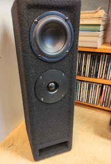
Today some vintage PMC LB1 studiomonitors did arrive at my desk.

For those unknown: just follow the link for a description of these UK manufactured benchmark loudspeakers, developed by some former BBC employees.

They came accompanied with a assorted collection of 'spare' tweeters and woofers.


Upon first test nothing worked as it should: we quickly found that both 1 and 2 +/- connection of the speakons where paralleled. Now that is a bit unusual, as in pro-audio we use a NL4 speakon to feed a loudspeaker with a high/low split signal. Nowadays the majority of prof. amps have 2 channels feeding 1 speakon. So the box effectively shorts the 2 channels. Not good. Oh well..easily sorted.


Still not very good sound. So let's open it up: and behold and wonder some fire has been inside.

Now this really made me curious. I know the loudspeakers have been driven with Bryston 4B amps. (Not to shabby!) So underpowered clipping amp couldn't be the reason.

So let's investigate...


First thing I did was try to find a schematic for this cross-over online. No luck.  So I drew it up myself:

Now to get an idea of the design philosophy we examine the values of the components closely. Immediately the doubling of C1 vs C2 (6.8uF) springs out, which will point to a textbook LinkwitzRiley 24 dB filter. In those days modelling software (like LinearX Leap) was available but apparently not wide spread. (I did acquire my copy somewhere in 1996). So we could investigate this pointer further. I de-soldered the 2 coils and measured them. Not very accurate, but both values and even more their ratio (1:4.5) prove this indeed it is a textbook LR filter.

To determine for what crossover frequency they designed that filter we have to do a bit of guess work. because you will have to know the impedance with which this filter is terminated. What if they just took the (DC !) 6 ohm resistance that is mentioned on the tweeter ? (of course this is not correct but read on..) In that case the crossover will work as a (electrically!) perfect 24dB LR crossover at 2100 Hz.

Anybody who has dabbled a bit in passive crossover design knows the horrors: components all interact with each other, are never ideal (parasitic inductance / capacitance)  and the terminating impedance is never a constant (ohmic) resistance. So yes, changing f.e. capacitors with different brands (with the SAME value, duh) will have an impact on the sonic behavior of a filter. But that is a different story.

First let's measure the tweeters to see if that terminating resistance indeed is more or less a constant 6 ohms..


And yes: the green line is an impedance measurement of the raw driver. That is rather flat to begin with so one immediately thinks: ferrofluid . Indeed in the '90's that was considered quite the bomb. Some manufacturers did use ferrofluid in everything (even 15" speakers, bad idea!)

One of the 'spare' tweeters had some note saying "possibly faulty", so I opened it up to find out. 

Now opening up drivers and in general reconing or refitting new membranes is NOT a good idea (with nowadays manufacturing tolerances) but that is an other rant, this tweeter was 'possibly' faulty anyway:

Yes, JL (in 2015) this tweeter is definitely faulty..I might even say totally foobarred.. But also filled with (a bit dried) ferrofluid so: confirmed!

Now what type/brand tweeter would this be, because they look awfully familiar?

And, suprise, suprise: when I pulled away some PMC branding sticker I found the original VIFA D27TG35 sticker. Take note of that exact number because this is remarkable!: In that same era (somewhere in the '90's) I did design and manufacture  a small multipurpose loudspeaker (build maybe a 100 units or so) with that exact same tweeter. When they went out of production I bought the remaining stock and that was the end of that build. (fairly recently I did a restoration of one of the installs-->)


And no, some Peerless or (Vifa rebranded) tweeter with a similar number will not be a replacement! But you can have your own opinion: nobody will get hurt..

Onwards with the filter, cause still some components need to be explained: more precisely the burned resistor(s). First one is a series resistor with a paralleled capacitor. This will serve as a attenuator for the tweeter and also as a slight top boost (ferrofluid, y'ken) with +3dB point at 9khz. Fair enough. But it will make the filter 'see' a higher load.

But what's that 100nF (with series 8 ohm) doing there? Those values make no sense at all, it does precisely nothing in the audible band. Also as an zobel network (to stabilize amp load) it is nonsense in that position..oh well.. brainfart from the designer??

So this leaves us the one resister that is paralleled with the combined load of tweeter and attenuator to get back to the correct load for the LR filter. From a designers perspective this is an awful solution: that resistor will get hammered with a lot of power, so no wonder it is burned. 

Previous repairs show a (also way to small) installed 13 ohm resistor. Now that's an odd value. Not likely in my opinion. 

Back to the measurement above: if I insert a 10 ohm resistor and re-measured the tweeter with attenuator I got that yellowish line: an almost flat, straight out 6 ohms, which brings us back to the desired, flat line 6ohm for our LR network topology...

Now hows that for loudspeaker forensics?


..on to Part 2


PMC LB1 a historic investigation in legacy sound, part 2

 Part 2

 ..on wards..

So now what will we do? Upgrade that filter with audiophile components?  Redesign it with what we know now? Or even use some DSP to make an active system?

NON of the above.

Audio reproduction is a construct so if we want to know why that box was so successful in those days we have to thread really careful!


So what I did was replacing those burned resistors with beefier ones of the original value. However, I did get rid of that mystery non working 100nF to make some room. Purists forgive me if you hear a change in the 200kHz region.

I also replaced that electrolytic cap with some MKT  I had lying around. We all agree that (old) electrolytics are a pain, right?

They serve as impedance-equalizing for the woofer so not in the 'signal path' anyway.

So how does it sound?

At first I was a bit underwhelmed, so let's look at the measurement to see if I perhaps made a mistake by swapping polarity of one of the components . (note to self, why don't you ever mark down how things where connected?)

No, totally correct. As expected: perfect all-pass behavior. Also the inverted tweeter experiment gives a deep null.

It does sound that way too, like a well balanced loudspeaker. Albeit it bit dull and boring perhaps to much zero-phase-fir-filtering for me lately?

puzzled...


..So let's turn it up and see what happens...

AHA !! Euphonics !! I can do euphonics, after all I have been a live sound engineer for many years. So I need a bigger amp, as I was testing with one of my whimsy yet brilliant sounding gain-clone-single-chip amps. 

Unfortunately I don't have some spare Bryston lying around but I do have some class A amp from a prior experiment.

Now stuff starts to be clear why people have blown these speakers into smithereens: they just say more more more more more..

More off what? More of that fantastic low-end! That tweeter I do know: not the best 7kHz I ever did hear, but that transmission line is real fun!

Here you go: measurement very close to the port. You can see the smoothly playing 60Hz (such nice frequency)

But it does look a bit worrisome around 220Hz, right? That's a general problem with transmission lines, maybe I can repair that a bit with some more experimental stuffing

Now will this loudspeaker work as a generic monitor loudspeaker in 2023 ?

We would first have to define what a monitor speaker is. 

Contrary to some big names in loudspeaker-design-industry (not studio people), I have the feeling that working as a mixing engineer is also a part of the creational phase. Not re-production as in playing back the end result.

So a studio monitor is not there as a reference of the end result but to make you do your creative part in a stimulating way. And press you to reach further, higher, better, newer.

These monitors came into fashion when we (in live sound) started working with band pass (6th order) subs..and hey: let's try some Portishead / Massive attack and drum 'n bass (Propellerheads!)

...woohaaaaa... this is the shit..damn!

How revealing is that!

Now does recent music like Billie Eilish, Whispering Sons, (modern) classical music work? nah, unless you really enjoy that '90's sauce on everything.


That being said: some of these sound system blokes are experiment a lot with 1/4 wave sub, as if it is something new.. So who knows what will come into fashion again, after all everything seems to go in circles.


And another day of listening + experimenting: Red line is port measurement without any additional stuffing, whitish line is with some extra 'sheep wool' stuffing. Sure: low end is cleaner + sounds more tight with the stuffing but the 'fun' is gone.. 


More research is required: I will use the extra parts to make a home brew TL and in the meantime get a better (DSP) crossover because the groupdelay of that conventional filter is starting to annoy me. The restored boxes will serve as a reference (in my memory database) to that.

Keep checking!

PMC LB1 a historic investigation in legacy sound, part 3

 Part3


As I mentioned in the previous post: I was getting annoyed by the overall group delay as it is introduced by the text book IIR (LR 24dB/oct) filtering.

So here's the experiment: home brew TL with a very cheap 4" speaker. I totally forgot to take pictures of the making, not that interesting at all: it is a standard 1/4 lambda backloaded TL with some folding. 

Very similar to the PMC design

The big difference will be the filtering: I used one off my DSP boards to make a overall zero phase shift X-over using FIR filtering. How to do so will be a topic for a different series of post. Soon. Maybe.


While presenting them to my audio peers it became clear to us that there's no way back to IIR filtering once you have tasted the reverberant field as it is presented by a zero phase system..

But that wasn't the topic of this experiment. We where investigating the sonic properties of a Transmission Line. Funny coincidence: right at this moment the Amsterdam Dance Event is happening and all newspapers are full with interviews with the current stars of EDM. Accompanied illustrations show pictures of studios with big (PMC) transmission line monitors. 

So this is hot stuff at the moment.


 Now how does a TL sonically compare to a different approach?


Very same speaker, different hornloaded tweeter but we can ignore that. Literally. We have been practising listening for some time.

In this small cabinet I used a digital implementation of the Linkwitz Transform to get some LF response squized out of that wee speaker.

In the STM32 part of this blog I did talk a bit about the intricacies of this.

So we now have two things to compare AFTER each other. As always when listening and evaluating audio stuff: you have to remember it for a few seconds. Which isn't simple and definitely needs some training..


How do they compare?


Purple line is close to the port of the TL (transmission line) while the green line is close to the speaker of the LT (linkwitz transform) closed box.

Clearly the TL has quite some lower response around 60 hz (again, such nice frequency) all though at the cost of a bit funky phase response.

Forget the resonances at 180, 300 (hey..odd harmonics..hmmm) they certainly spoil the fun in this experiment and are the main reason that some music really shines while other sounds horrific. Missing fundamental psycho-acoustics at play here.

But we are not finished yet.


I totally like that 60hz. From such a small box. So I made another, bit bigger TL with a 10" speaker. Right at this moment it is playing at my feet under my desk. Also at actual quiet levels it really does bring an extra dimension to the genre I am currently digging in:

Hauntology 

(EDM is too boring for me)

So you can get an idea of the sonic landscape.


Now what about those pipe harmonics in this setup?

Well, very steep FIR filtering at 80 Hz proved to solve that.

How? By using down sampling to a sample frequency that doesn't take zillions of coefficients to get the desired resolution of the linear phase filter.

Naturally (a lot of) delay has to be added to the (high end) desktop speakers. 


And now things get really interesting: 

I never was a fan of 'separate' sub woofers. Also in live sound. The setting of delays from subs to mains or vice versa always is giving you grief when they are some distance apart. Most certainly if you understand what phase-alignment involves.

Why would that be as wave lengths around those frequencies are in meters? So how could some centimeters make a difference? Well maybe the (much higher in frequency) harmonic distortion produced by subs have to be in time with your main?

With the above very steep filtering I could, at least at lower levels, get rid of that distortion and now the sub is behaving as it should: it seems as if my wee desktop speakers are producing a tremendous amount of accurate bass. Most certainly with instruments I know well (like bass guitar)

I also tried a similar setup with a conventional cabinet, but that doesn't give you the same results: a TL has a lot more efficiency at the freq. of interest, meaning the cone has to move less and thus produces less distortion compared to an (augmented) closed box.

So that leaves only the quirky phase response (at 60-70hz) from a TL to be evaluated against program material. (I could differentiate it to get the groupdelay to get a better insight)

Let's see..

..Audio reproduction is a construct..


Making a DI box

Over the past decades making a DI box has been one of my recurring activities.

From repurposing scavenged  transformers into make shift 'passive' boxes to  experiments with unbalanced to balanced chips.

The problem is phantom supply. 

All though rated at 48volts it's purpose as a PSU for any circuitry is really limited, because the way it is implemented in almost every mic pre-amplifier:

The 48 volts is fed through 2 resistors of each 6k8 in each leg of the symmetrical input, thus giving an impedance of 3k4. Which means that if your circuit draws say 10mA of current only 14 volt of that supply is left to begin with.

Your own circuit will have some resistors in the supply lines too, to unload the output from your circuit. So the voltage to work with and thus the headroom of your DI will even drop more.

Hence the really limited headroom of a lot of modern, commercial DI boxes

Old skool '70's electronics to the rescue: 


This circuit is no rocket science and well known in every pro-audio circle, mostly credited to Bo Hansen..

Quite a few mods though, just as a reminder for myself a picture of the early limited (as in only 20 pcs of that specific transformer in my very old stock) prototype:


By popular demand we decided to try to do a reissue fairly recently.
The problem was finding a nice affordable transformer: these Swedish ones are really nice, but man, do they charge..Pure by coincidence i stumbled across OEP. Now those i do remember from the classic BSS AR116 DI. (Which has nothing to do with the modern AR133 !!) And with some googling I found them to be used by modern Telefunken as well (speaking of brand name marketing!!)
 

So here we go a batch of class A, current driven, transformer balanced DIs in a stainless steel housing. 
Yes, stainless steel. 
Every DI gets abused once and awhile as a stage weight, box tilt, or even as a hammer so to prevent them from changing into ugly lumps of corroded, dented metal, we folded and water jet cut some stainless steel sheets:
(of course I didn't do it by myself: credits to Koos Roadservice)


Still not totally satisfied by the end result I learned myself how to powder coat (not difficult at all) 
 
So here it is..open for orders now..hahahaha...

KBLsystems class A transformer balanced DI


Fighting long boot times when using older RPI

It has been quite a while when did my 'audiophile' music player built.

raspberry-pi-with-balanced-output 

It has been almost a decade now and there is a zillion of dedicated distro's around to make this really easy.

Just google: RPI musicplayer.

All really nice and slick..but..taking..ages..to..boot, certainly on older PI's 

So while reviving this old project to include a transformer balanced output, (driven with a class A running NE5532! ) I worked myself through the big pile of clogged info to get a faster booting system.

Now the easiest way would be to get yourself a custom build image using a build system like buildroot, yocto, openwrt.

I did have a go at all of them but the easiest way to get yourself (like me total noob) going would be to start off with buildroot.

Just follow the walk through (maybe add in a SSH client like dropbear) and you will quickly get your own fast booting image. That is: it isn't complicated but the compilation takes hours!

The bit more nasty part comes when you want to take it further: not many people talking about this, so for future reference here's some reminders.(as long as this will be of any value in the allways changing wonderful world of linux 😂)

RPI has it's own rather special way of booting at which time you can configure all kinds of hardware add-ons by using so called dtoverlays.

If you have been working with RPI and audio you will have come across these: to configure edit the config.txt file in the 'boot' partition of your disk image. (sometimes it will have just a number instead of the name 'boot')

For a first test add 'dtparams=audio=on' to this file. This will select the onboard shitty audio out. In theory. But the inner workings of linux in these buildroot-builts don't seem to be loading the necessary kernel modules. Something with udev and dts / dto. Complicated stuff. Tell us when you know how to do this!

I got it working with 'modprobe snd-bcm2835'.

We did select the packages to get alsa and other obvious stuff like mpd, mpc and a texteditor in our simple build, right? 

Now to play some music (from that USB stick) you will have to mount it first: 'blkid' will give you a device name or UUID, create a mount point and mount. Configure '/etc/mpd.conf'  to point to that music directory and also add a default alsa-audio-out setting while you're there.

Restart MPD: first kill it by PID number found by 'ps' then start by mpd (no sysctl or systemd in default busybox) . Now mpc will have hopefully controle and some information on mpd.

Now on to even more remarkable easy to forget nooks and crannies:

We do want that i2s-dac thing running.  In the picture is a simple (i2s-slave) interface that doesn't need any configuration (by i2c). I think most of these simple boards will work, this one is an old hifiberry-dac with a pcm5102a. That is a significant hint to get it going:

First comment out the 'dtparams=audio=on' and add in 'dtoverlay=hifiberry-dac' in the aforementioned config.txt file.

But you will not have any overlays in that 'boot' directory. So download it from some github or strip it from some other distro. Probably kernel versions and .dtbo file will have some relation...

Now for the similar modprobing:


You need the 4 of them to get it going:

snd-soc-bcm2835-i2s, snd-soc-core, snd-soc-pcm5102a, snd-soc-rpi-simple-soundcard. 

Finally! Audio from your i2s board!


Now to make it persistent after reboot, you have to make a little script in the '/etc/init.d' . Give it number some lower as the mpd-start-stop script, which in my case was S95. (that's capital S!)

Don't forget to mount your USB-music-drive before starting mpd. I edited the mpd start script to mount the drive: the usual fstab methode doesn't work to well. Presumably the default mpd start script will be started before the USB drive is ready for mount.

Other nice stuff to implement:

We can us sysfs-kernel modules to manipulate GPIO ports. Make sure the pins are not in use for other functions (like i2s..duh). Here is a small script:

 
 1
 2
 3
 4
 5
 6
 7
 8
 9
10
11
12
13
14
15
16
17
18
19
20
21
22
23
24
25
#!/bin/sh

#gpio17 to drive a led:
echo 17 > /sys/class/gpio/export
echo out > /sys/class/gpio/gpio17/direction

#gpio27 to have a push button to do "mpc next":
echo 27 > /sys/class/gpio/export
echo in > /sys/class/gpio/gpio27/direction

while true
do
if mpc status | grep -q 'playing'; then
  echo 1 > /sys/class/gpio/gpio17/value
else
  echo 0 > /sys/class/gpio/gpio17/value
fi

if cat /sys/class/gpio/gpio27/value | grep -q '1'; then
  mpc next
fi

sleep 0.5

done


Oh, and one more thing:

Before starting to use something like 'buildroot' think of a way to separate everything from your everyday-work-computer. It will give a big mess if you don't. I used VMware. Do configure for plenty of drive space!


TAC Scorpion revival

Back in the days when everybody was using some Soundcraft n*200 (n = 1,2,3,4..) mixingdesk I used to prefer a TAC scorpion console. We are talking end '80 begin '90 here..

So this is my, way to much work, project to investigate why I did prefer that console over others and at the same time make it a bit more 2022.


Now this is most certainly not how these consoles looked, so lets start with a picture of a original TAC Scorpion:

This is not my original console, that one has disappeared into oblivion. But very similar to the one shown on the left, all VU meters where broken. They all had that after a year or 2..

So instead of trying to fix those first thing I did was get rid of some heavy metal casing. Boy are these things made like heavy armoured tanks.

I do like VU meters on every channel though! Not as much to adjust gaining (o, man I can rant on about that one). But they really come handy to quickly see which synth/sequencer/voc channel is doing that solo in a live situation😏

So I made a VU board with a vintage chip everybody knows: LM3915. As there is no audio  passing through this chip I didn't care where it came from: Aliexpress FTW! I did design a simple pcb in cool black and here you go diy VU meter:
I mounted them to the faders which I had to clean anyway. And I used the same feed point for fader and the measuring entry (as in PFL), so no long lines running across the console..


..to be continued

Working Distortion

Those friends that know me from real life, will have heard me sighing in despair:

Audio reproduction is all and only about hustling distortions around.

Aside from all (FFT-) techniques that should be common knowledge by now, we still have a long way to go in having our parameters to describe 'good sound'.
First statement to make:
Audio passing from one end to another can never be 'better'.
Be it a microphone, loudspeaker or any electronics.
So if it only can deteriorate: then audio engineering boils down to manipulating in which way it get's worse.
Isn't that sad  😥

If we manage everything correctly in the frequency domain, as described here in this blog, then what's left?

Distortion!!

Sure we all know this should be minimal, shouldn't it?
And we all express it as THD, oh wait let's add in N(oise)  too!
Not a very elaborate way to express what we are trying to study is it?

And why are all these Waves plugs so highly loved and wanted?
Tasty spices also known as harmonic distortion.

Check my current home-brew study object:


Raspberry PI with balanced output

As a sound system designer you will, at some point, need a source to test your endeavors.
Apart from saying 'test one two...'  for hours on an end in a torn SM58 microphone one could also use some music.
More pleasant for the people around you and you will have the added advantage of having your hands free to twist those nobs..;)

Those soundguys being around a bit longer might remember the confusion when CD arrived. Away with the crack rattle noise and buzz from these LP's (let alone cassette copies) and hey, wow, what a clear definition, but wait a sec, what is going on in the top-end?
However the method of testing and tuning your sound system with your favorite CD became a world wide spread practice.

Now fast forward: we are in the 21st century, skipping Cd's are obsolete and a lot of people will use their ipad/pod/tunes to perform their tunings.
The lot of them will have some doubt regarding the quality of mp3 and advocate the one and only use of wav (or flac for our open source friends).

Certainly, we too have been using some CD's and a 'high-end' hifi CD-player  to do our system tuning.
But, although we never did a serious investigation, we always had some suspension regarding ripped CD's playing from some OS through some USB interface.

Now enter the realm of playing music from your computer.
First you will notice that it really does matter a lot what brand of interface you will be using. In pro-audio the most common solution will be some RME interface (pricey!)
If you investigate that route further you will notice that it also does matter a lot what player (read codec) you will be using: foo-bar being one of the more popular as opposed to anything like 'windows-something-player'.
Being on this route you will also find out that you have to bypass all OS based up and down sampling, Wasapi might be a solution in a windows environment.

I decide to take an other route:
Linux.

On several instances through this blog you will find pointers, a year ago or so f.e. I started to write a (never finished) walk through in setting up a headless music player.
Now let me try to round it up:

Raspberry PI running Volumio with balanced outputs


Well, with 5 million of these boards sold, one can presume that you have at least heard of Raspberry PI.
Rpi is based on one these so called S(ystems) O(n a) C(hip) running a linux based OS.
Actually at first marketed as a entry level platform for children to get to know programming it seems that these nice toys are becoming very popular with grown ups. Ahh, well, toys for boys I guess..
On a zillion places on the internetzz you can find information and howto's on operating a Rpi.
Let us concentrate on running audio.

First of all the on board audio chip really sucks, so first thing to establish is to get your audio data of the board in a proper way.
Now you could use some sort of usb based device, maybe even the above mentioned RME DAC's, but I had a lot of trouble running bigger data streams (24bit/96k) across the combined USB/ethernet interface.
Apparently just not up for the task.

A different route only recently opened up by using the i2s protocol on gpio ports.
Several people have been making nice add-on boards that sit on top of your RPI.
Here is three of the boards I tested:
Wolfson

Duriosound

Hifi berry digital

The 4th is a board from Hifi berry and puts out analog.
All these boards perform similar. (no, this is not turning out to be a board shoot out ;)
For the story we will continue with the latter:

modded HifiBerry analog in place

As has been mentioned before and over: two things of importance in 'bit perfect' reproduction of digital audio:
1.  no interpolation by up, down or oversampling and no arithmetic functions like 'replay gain make up' or any other mockery should be happening between your audio file and your D/A converter.
2.   clock should be as stable as possible.

For the first we trustfully use MPD playing audio directly through ALSA (i2s). Volumio is a very nice Linux distribution which takes care of all these software nooks and crannies which are explained in other places. Just google the key words.
The second is a bit less documented, you will find people arguing against RPI because to derive a sample freq. from 44100hz you need a fractional division of the RPI 's clock freq..not so good..
48k / 96k should not give you that set back.
Do I feel that as a big problem?
nah.. Remember we are talking a 100 euro device here so don't expect 1K+ euro performance!

But let us try to get a clean clock signal in the first place.
The guys who really know things about digital audio like Guido Tent (Tentlabs) or Eelco Grimm (Grimm clock) have whispered PSU in my ear.
So first step in improving the basic setup was to get rid of the wallwart switched mode usb psu:

linear PSU using LM7805 with 2N3055
Very simple linear PSU with the well known LM7805. To boost the current a bit I used a parallel 2N3055 (think 70's for sound ;)
All very well known basic techniques.
I did use a mix of some fine electrolytic capacitors in a experimentally achieved witchcrafted constellation, though...


Next thing to do is to make a balanced output.
Pro-audio guys really hate unbalanced signal transport: introduction of rattle and hum being the most mentioned spoilers of the party.
But what if a asymmetric transport is anyway a fundamentally wrong concept?
Treating 'earth' like something solid might be a right concept in high voltage power distribution, but  is completely wrong in signal transport (imho).
Naturally it takes 2 conductors to transport a signal and they are both equally vulnerable to the introduction of all kind of disturbances.
Gold plating or Teflon insulation of a single conductor does not help in any way.

Here is a picture of the circuit with it's separate dual 15v PSU:

unbalanced to balanced with That1646 and TL051 driver
The TL051 preamp is selected from a range of opamps using the still 'golden ears' of my 13 year old.  :)
Being past 55 I think mine have been deteriorated  to iron/lead/wood by now.
Remarkable sensation, knowing it's there but not being completely sure, like looking through a stained glass window.
Oh well, experience replace the loss (I hope).

Lastly a picture of the finished 'product' in a vintage AKG phantom supply box :


Active X-overed HiFi ?

In the Netherlands we have this expression about plumbers always having leaky taps in their homes.

Sooo 
While business being on the slow side I decided to upgrade my personal hifi / mediacentre sound system to something with a bit more throw and detail.
Having so much stuff from prior experiments lying around I made it a design restriction to myself not to buy anything new.
This worked out to be a much longer lasting effort than I calculated for.
Three weeks in a row of precious time wasted (?)
Oh well, let's call it educating myself.
Let me try to give you a condensed report..

Design imperative was to build a small system (needed to fit in the bookshelf) with enough throw and definition to listen music at very low levels at night while the family would be asleep.
For that we would need FIR filters and so a Soundweb 9088ii will be at the hart of it all, see my prior posts on the upgrade and repair  of these nice tools.

Next thing would be the speaker cabinets themselves.
Top-end wasn't going to be that time consuming where as I was to recycle my priorly build tractrix waveguides.(also see previous posts)
Loaded with some DH450 drivers from my preferred, and highly appreciated supplier A&D-audio

rearview
frontview

Now why is that resistor in series?

Three reasons: 

First of all, evidently this horn/driver combination will have a lot more gain than the accompanied (hifi-) mid speaker.
So a big attenuation in the digital domain would be needed to overcome a magnitude mismatch.
Rather than choking on the associated loss of digital headroom/resolution, I decided to make a passive attenuator.

Secondly the amplifier will have to make some amplitude swing so distortion introduced by the amp (class AB crossover distortion) would be relatively small.
For some reason (presumably distortion associated) I also like the sound of warmer electronics (warm not hot!).
Ok, ok writing this I detect mumbo-jumbo alert, but believe me there really is a difference.
While I don't have the engineering skills to explain this difference, this doesn't mean I am lacking in, on firm science based, perceptional skills!

Third and not the least:
The driver amplifier combination will now operate in a (partly) current drive mode (again also written about in a prior post).
Naturally we now have to use some (min. phase) EQ to compensate the magnitude differences introduced by the impedance curve of the driver in series with this resistor, but the overall reduction of distortion is quite convincing.


Now for the mid speaker:


left is hifi      -      right is PA

From the maximum total cabinet hight of 28 cm (had to fit in the bookshelf, remember) I now only had 17cm left.

In pro-audio industry more and more smaller speakers are being used in those line arrays you see at every bigger event.
So (being a pro-audio designer) one would say I have plenty of sample speakers lying around to be used as this mid speaker.
Quite disappointing!
From all the samples I tested  (yup, a lot of 'big' names) the only one remotely optional for this purpose is the one shown in the picture.
(This experiment alone actually took a whole working week, so fast forward here ;)
Does this imply that all PA speakers are horrific?
Yes and no, for this purpose they will not be suited in a same way as a hifi speaker will not rock you.

Although this statement seems quite obvious one really has to add in a lot of question marks here..why?..

Actually this is a pledge for a paradigm shift in our industry.
We neither have the tools nor the (scientific) language to quantify the above described statement.
Surely this has something to do with distortion but how, what, why?

Anyway, for the purpose of the story let's continue with this Seas mid speaker.
In the pictures above you can still see an open back.
Actually being a bit too lazy to do a proper cabinet tuning (either closed or reflex) I thought this dipole configuration would be a good idea.
Stupid!
Horn loaded, zero phase shift, directed high's don't combine with room loaded low's..
So in the final cabinet this is a closed box (with luckily the correct volume for a .7 tuning)

Same thing for the subs which I made from some no brand speakers I had lying around.
Nothing special here, only highly over dimensioned for the purpose, in that they all ways will be operated in their linear region only.

soon follow up on electronics and (FIR) filtering

for now here's a preview of the final result:


Bringing Soundweb greens back to live


We are still using quite a lot of  old green Soundwebs 9088 and 9088ii in our soundprojects. The main reason being  that these ancient machines were allready capable of some FIR filtering.
Mind you: there is a bug in the software which makes you have to reverse the filter kernels. Presumably nobody ever noticed using linear phase filters (symmetrical as these will be) ;)

Anyway I had some broken ones lying around so I thought it would be time to do some repairing.
One of the apparent vulnerabilities is the power supply cap marked as C216.
So after replacing these I was able to get some off them back to live.
For all you out there plagued by the dreaded searching.... (at infinitum) modus I will repeat some 'rules':

  1. replace C216 cap, while you are at it maybe it's a good idea to upgrade cap C265 with something beafier as well.
  2. use the spare jumper at the option A position to set your machine in debug modus.
  3. switch on power, you now should get the 'nightrider' row of flashing leds.
  4. use the backup loader.exe to reload the firmware. make shure you have the correct *.a21 file. I learned the hard way do not to make a mistake!
  5. when done switch of power, replace jumper and reboot.
As allways use correct settings of com ports and bitrate (38400 front, 115200 back). Also the FTDI driver / USBtoRS232 works fine on windowsXP (and 7) but on windows 8 it appears to be troublesome.

Now for the fun (and utterly time consuming and by no means commercially viable) part.
Let see if we can do some 'audiophile' modifications.
In the issue 1 model (9088) there are some VCA IC's build in to facilitade volume controle directly after the DAC's.
These suck! ;)
I forgot the type number but in a earlier experiment some years ago I removed these and  shortened the signal path. So no more volme controle on the output and maybe (with high gain power amps) a bit excessive noise.
But hey, who cares for noise?
It's the universe coming through our speakers!
Big plus!


Next thing I thought would be whorthwhile is replacing all these (non-polar) caps in the signal path.
Well this wasn't going to happen.
All my regular dope dealers like Farnell and RS and the like seem to have stopped selling these, hmmm, bummer.
Now what if we replaced them with regular caps back to back with a DC bias.
(This is an idea I actually stole from a very old Midas PRO4 console I once owned).


Big improvement?
Argh euuhh, yes with all my skills I can notice the difference (some more clarity) but I 'm not even shure if this is desirable.
So, nah not going to do that on all our machines...

 ...edit...edit...edit...
Not completily convinced by the dispointing results of the above modification I decided to give it a second try.
Same mod but this time I tested a stereo a/b comparison..wow.. this is some serious shit.. much broader and deeper image and a very convincing musical impact..now why the hell is this???

LouReed with new carbon cone speakers

This summer the shipment of our brand new carbon fiber speakers finally arrived.
The first listening test worked out quite promising, so we decided to upgrade our LouReed systems with these babies.
Nico is going to use a set of these speakers for some complicated acoustic performances during itgwo , so the design goal of the adjusted filters would have an emphasis  on producing a clear natural sound.
As opposed to rocking your guts with e.g. Rammstein, that is.
Probably Sebastiaan will call this boring (I guess) :)


By looking at the speaker you might expect a really full bottom-end with long excursion bangs of the speaker like 'car' hifi speakers do.
Not so!
Fortunately in this case 'cause that would bring also a lot of intermodulation distortion. Think thumping yourself on the chest while singing. Not looking for that in this case.
So why a rubber surround? 
As is the case with al stiff materials in speaker design, shurely they sound a lot better: stiffer cone -> stiffer piston movement -> less break up distortion.
But when they do breakup (and at at 'our' levels they always do): HORROR.
Remember the 2' titanium vs 2' aluminium driver diafragm 'upgrade' problems?
Or the special sound of that A brand line-array with yellow speakers for everything, when you hit it real hard?
Well here comes the genius of our Chinese friends: the rubber surround will absorb those hard breakup modi! Brilliant!
 
I also tested a other speaker in the same cabinet.
From the front the cone looks like your standard 12' (guitar) speaker.
Soundwise this gives you that nice zzhangg you are looking for in metal guitar a la Rammstein.
Not that pak-pak from a modern plastic coated speaker (think 'french' PA's).
So what's the Chinese ingenuity here? Back Coating! 
Al the advantages of a stiffer cone by coating without the ugly breakup. Again brilliant!


So in fact we now have two recipes for our LouReed systems
Does this mean a different magnitude/phase slopes of the overall response?
No, certainly not, actually the final results show quite simular curves.
Does this mean different EQ needed to match or linearise the responses?
No, also certainly not, actually in both designs zero EQ was applied.
(to the speaker that is)
Shurely, different program material makes me want to apply different micro EQ (no more then 3 dB, Q<2, that is), but I always end up in bypassing them again.


Which will have to bring me to the next topic:

Distortion matching as a design goal in loudspeaker tuning


oh, euh, yes, by the way: all the time we are talking distortion here I mean that very-fine-grained-hardly-noticeble but still quite -important-emotion-wise effect for which I don't know how to quantify else then by using my ears...

LouReed rises again..

More over one and half year ago one of our 'LouReed' sound systems was stolen from a parked van.
Surprise, surprise  a attentive civilian found this in the woods recently:


Shock and horror, our meticulously crafted cabinets tossed away!
Probably not useful for the people who stole them as they need to be operated with a separate (FIR-filtered) X-over to get anything like alone a decent sound.

Today I have been refurbishing them and to my really big astonishment: the 12" speakers are still full-spec functional. Hooray for mr Simon Leung (A&Daudio) for the excellent manufacturing quality!
The 1' drivers were less fortunate, not that they would be of lesser build quality but of course these are a lot more vulnerable.

So here comes LouReed Phoenix..
While we are at it we will also update the FIR filtering for these cabinets.
For those interested in FIR: Thomas Drugeon (AKA pos) made this excellent utility:
rePhase


And, oh, yes, I also made a quad amplifier using Hypex UCD400 blocks and a switchmode PSU.
If now we could find some decent DSP modules (with FIR!!) we then finally could make our powered cabinets.. (nah, sorry no minidsp, nice but not stable enough for our "pro-audio-abuse").
Might have an other idea though..will get back to ye.