Showing posts with label blurbs. Show all posts

Dynamic lin. phase EQ..some trials..

Linear phase EQ, part 1

First let's talk about EQ in general:

A few decades of running a sound-rental left me with a huge collection of superfluous copies of several brands of 31b. graphic EQ's
My personal favorite was such a KT DN360-->


What was (still is??) the purpose of a 31b. EQ inserted in the mains of our PA's?

Often people start jabbing about room EQ, tuning a system to a room or other semi scientific nonsense never leaving out to mention phase issues..

Once you grow to be a bit more aware about what you are doing you will realize that the use of such a graphic has (had) two purposes: 

1. you will use it in the creative process of doing your mix

2. you will try to correct problems you are experiencing with the current program material, the system (and the level)

The first one is not at debate here, let's investigate the second topic.

Loudspeaker systems in general are giant distortion generators (as compared to electronics). To elaborate on the cause or specify what distortion would lead way to far in this article, just bare with me and do understand that we are not talking about rattle and buzzes but the harmonic distortion as we sometimes also appreciate.

So with this in mind we could agree that the tweaking in the 2-4kHz region on your graphic might be triggered by the perceived distortion.. NOT the level..

If you remember: you dipped that frequency because it was 'ugly' not because it was 'loud' 

All analog EQ's and the mayor part of it's digital counterpart are min. phase. Meaning: yes, every EQ setting will affect the phase in that region in a way as is associated with it's magnitude response. Law of physics. Mostly no problem as in the thing you are correcting will be min. phase too.

The example above: using your EQ to dip those ugly distortion will affect phase in a way you don't want. Maybe that's the reason you keep tweaking in that region during a 'difficult' show.


Another reason why you keep changing the EQ settings in that region could be Fletcher + Munson.  Everybody knows these equal-loudness contours. The 'loudness' button on your '70's hifi amp is a direct consequence.

Look closely in the 2-4kHz region, not only your hearing is more sensitive in that aria (duh) : 

Also that sensitivity changes with level both in freq. and amount. Go from 80 to 100 dB to get an idea.


We do have tried different solutions for this. I never was happy with any dynamic EQ or desser function on any compressor of any of the shelf product.

Multiband compressor techniques are more something I could appreciate. True lin. phase that is! Here is an example of a way I did this using a free programming platform like BSS soundweb:

The signal is split in two pathways by using lin. phase FIR filters. Great care has been taken those filters when recombined don't affect the signal in any other way then adding in some delay. Both paths are compressed with different settings for attack, release, rating and so on. The compressor is made more 'sensitive' for the freq. of interest by using an EQ on the side chain (having its split feed before the FIR will give it some 'look ahead')

Still not quit happy as in you don't want a 'compressor' action, you want 'EQ' action.

So recently I started to experiment with my home brewn DSP boards. I took a metal horn driver combo, despite the felt damping it will have a ringing-bell associated distortion, certainly if it is not mounted firmly in a box. (still a really nice, controlled top end, though)


..soon more


Dynamic lin. phase EQ..some trials..

Linear phase EQ, part 2


The fun in coding your own DSP  is you quickly learn this Egg of Columbus, once you free your mind of thinking in the frequency domain (paraphrasing Moroder):

Everything you dream up about multiplying functions in the frequency domain like applying dynamic EQ can in fact be a rather simple arithmetic operation in the (discrete sampled) time domain.

So EQ can work out as follows: apply  the reverse filter to the signal stream on a sample per sample base. Subtract that stream also on a sample per sample base from the original stream. Take care you do your calculation on the correct sample!

Mind boggling to realize that every single sample is a representation of the music playing (right at that moment in time)


void doProces(q15_t* Lin, q15_t* Rin, q15_t* Lout, q15_t* Rout)
{

	  arm_sub_q15(Rin, Lin, Mono, n);
	  arm_q15_to_float(Mono, Monofl, n); /*adding balanced input to mono signal*/

	  arm_fir_f32(&SLF, Monofl, Low, n);
	  arm_fir_f32(&SHF, Monofl, High, n);
	  arm_fir_f32(&SEQ, Monofl, EQout, n); /*several FIR filters*/

/*RMS treshold + attack//release: blocksize=48, sample freq=48kHz --> 1 mSec per callback*/
	  arm_rms_f32(EQout, n, &rms);
	  if ((rms > 0.005) && (gainEQ<=0.8))
			  {
		  	  gainEQ = gainEQ+0.1;
			  }
	  if ((rms < 0.005) && (gainEQ>0))
	  	  	  {
		  	  gainEQ = gainEQ-0.005;
		  	  } 

/*scaling + actual EQ substraction*/
	  arm_scale_f32(EQout,gainEQ, EQout, n);
	  arm_sub_f32(High, EQout, Result, n);

/*revert float back to signed int. Lout = low, Rout= high */
	  arm_float_to_q15(Low, Lout, n);
	  arm_float_to_q15(Result, Rout, n);

}

That is a very crude bit of code to run the tests, basically I use some FIR filters to split the stream in 3 parts: high to feed the HF horn, low to feed the speaker. And a bell shaped EQ stream around 2200Hz to do the magic. Totally mocked up out of thin air (and some prior listening).

If you are really interested you can work out the attack//release timing and chosen gain slopes (also derived with some listening)
Now for the promising conclusions:

Yes. 

EQ-ing with dynamic linear phase EQ does help to create a loudspeaker that is way more versatile in that you can play it more dynamical (read louder) without being annoyed with that ripping horn distortion.

But.

Care should be taken in not to overdo the processing because it sounds like that; over processing. Also: as (live-) sound engineers we are totally used to how a all these elements like loudspeakers and/or microphones behave and in fact make use of the nonlinearities in the creative process.


More research is required..

Here is some food for thought: underlying is a measurement of the first 2 distortions of the HF horn under test.  We all know: 2nd harmonic is ok, 3th is bad, right? Now look where I choose (by ear) that EQ point: right at 2.2k where that 3th bumps up. (and 2nd goes down!)


Brown = SPL 1e harm.

Red = SPL 2e harm.

Yellow = SPL 3e harm.


Yet one more thing i would like to add: 

In my discussions with my great audio friend prof. dr. SA (you who you are) he once coined the phrase: equal-group-distortion. Naturally this is nothing, what he was saying is: it is the discontinuities and bumps in distortion patterns that make us jump into action..

PMC LB1 a historic investigation in legacy sound, part 3

 Part3


As I mentioned in the previous post: I was getting annoyed by the overall group delay as it is introduced by the text book IIR (LR 24dB/oct) filtering.

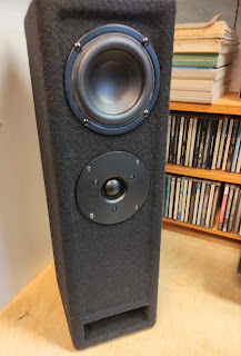
So here's the experiment: home brew TL with a very cheap 4" speaker. I totally forgot to take pictures of the making, not that interesting at all: it is a standard 1/4 lambda backloaded TL with some folding. 

Very similar to the PMC design

The big difference will be the filtering: I used one off my DSP boards to make a overall zero phase shift X-over using FIR filtering. How to do so will be a topic for a different series of post. Soon. Maybe.


While presenting them to my audio peers it became clear to us that there's no way back to IIR filtering once you have tasted the reverberant field as it is presented by a zero phase system..

But that wasn't the topic of this experiment. We where investigating the sonic properties of a Transmission Line. Funny coincidence: right at this moment the Amsterdam Dance Event is happening and all newspapers are full with interviews with the current stars of EDM. Accompanied illustrations show pictures of studios with big (PMC) transmission line monitors. 

So this is hot stuff at the moment.


 Now how does a TL sonically compare to a different approach?


Very same speaker, different hornloaded tweeter but we can ignore that. Literally. We have been practising listening for some time.

In this small cabinet I used a digital implementation of the Linkwitz Transform to get some LF response squized out of that wee speaker.

In the STM32 part of this blog I did talk a bit about the intricacies of this.

So we now have two things to compare AFTER each other. As always when listening and evaluating audio stuff: you have to remember it for a few seconds. Which isn't simple and definitely needs some training..


How do they compare?


Purple line is close to the port of the TL (transmission line) while the green line is close to the speaker of the LT (linkwitz transform) closed box.

Clearly the TL has quite some lower response around 60 hz (again, such nice frequency) all though at the cost of a bit funky phase response.

Forget the resonances at 180, 300 (hey..odd harmonics..hmmm) they certainly spoil the fun in this experiment and are the main reason that some music really shines while other sounds horrific. Missing fundamental psycho-acoustics at play here.

But we are not finished yet.


I totally like that 60hz. From such a small box. So I made another, bit bigger TL with a 10" speaker. Right at this moment it is playing at my feet under my desk. Also at actual quiet levels it really does bring an extra dimension to the genre I am currently digging in:

Hauntology 

(EDM is too boring for me)

So you can get an idea of the sonic landscape.


Now what about those pipe harmonics in this setup?

Well, very steep FIR filtering at 80 Hz proved to solve that.

How? By using down sampling to a sample frequency that doesn't take zillions of coefficients to get the desired resolution of the linear phase filter.

Naturally (a lot of) delay has to be added to the (high end) desktop speakers. 


And now things get really interesting: 

I never was a fan of 'separate' sub woofers. Also in live sound. The setting of delays from subs to mains or vice versa always is giving you grief when they are some distance apart. Most certainly if you understand what phase-alignment involves.

Why would that be as wave lengths around those frequencies are in meters? So how could some centimeters make a difference? Well maybe the (much higher in frequency) harmonic distortion produced by subs have to be in time with your main?

With the above very steep filtering I could, at least at lower levels, get rid of that distortion and now the sub is behaving as it should: it seems as if my wee desktop speakers are producing a tremendous amount of accurate bass. Most certainly with instruments I know well (like bass guitar)

I also tried a similar setup with a conventional cabinet, but that doesn't give you the same results: a TL has a lot more efficiency at the freq. of interest, meaning the cone has to move less and thus produces less distortion compared to an (augmented) closed box.

So that leaves only the quirky phase response (at 60-70hz) from a TL to be evaluated against program material. (I could differentiate it to get the groupdelay to get a better insight)

Let's see..

..Audio reproduction is a construct..


STM32 in final 'product'

Let me write a round up of this research on using a MCU as a speaker processor.

By this time I switched from KEILmdk to STM32CubeIDE which at this moment (november, 2021) seems to be the weapon of choice for most STM developers.

Again for future reference a quick how to on how to include a math / DSP library.

Together with your installation of the IDE you also will have installed some repositories for ARM software products. You are looking for CMSIS/DSP libraries. The path will be something like  /STM32Cube/Repository/STM32Cube_FW_F4_V1.25.2/Drivers/CMSIS/DSP/ in your home directory (in Linux). It will be similar in MacOS or Windooz.

Start a new project in the IDE, right click on projects name and Create new source folder. Name this folder DSP. Now again right click and select Import file system. Select both the source (source) and the header (include) file as in the screenshot from the above mentioned 'repository'. Click finish.          


Now you will have both the source and header files in your project but your compiler knows nothing about it so: right click project and find the project properties setup. Find the compilers include path settings and add the new path to your include file. Check the screenshot.

Now you can include all these nice ARM DSP tricks by:#include "arm_math.h" Try to build (that's embedded speak for compile)... Hundreds of errors, but if you check the firsts you will see that the compiler needs two PreProcessor directives. Find those in properties and add both: ARM_MATH_CM4 (we are using a M4 core) and __FPU_PRESENT = 1U (yes, we do have a floating point dohickey in our processor). O, and that's two/2 underscores! __


Now you can start programming your code making use of block processing, taking chunks of say 48 samples using the increased efficiency of the CMSIS libraries. 

Check all those filtering functions!!

There's loads to discover but let me disclose this one: 

Decades ago I met Ed Long (yup, the guy who 'invented' Time-alignment) at a proaudio trades fair. He demonstrated his closed box, single 15' sub. That was astounding (as was the excursion). His trick was to use electronics branded as ELF and not filters to EQ the sub. 


Much later Linkwitz developed a filtering method known as Linkwitz Transform. A similar way to correct the response of a sub woofer. 

Never got any good results with this method as in professional DSP's don't provide for a method to import your own Biquad coefficients. And using shelving filters and EQ will never have the required precision.


While using this CMSIS library function:

void         arm_biquad_cas_df1_32x64_q31 (const arm_biquad_cas_df1_32x64_ins_q31 *S, const q31_t *pSrc, q31_t *pDst, uint32_t blockSize)
 Processing function for the Q31 Biquad cascade 32x64 filter.

I managed to reproduce that sensation I had at that trade fair decades ago..Thanks Ed!

Do understand that you really, really need the above precision (in fixed point) to get any decent results! If you are into the math: understand how a biquad calculation works and how the representation of coefficients (which are all close to the unity circle) will effect the calculations at very low frequencies. 

(anyone remember we at some point (2010?) got this 'use for better LF response' check box in LondonArchitect? )

Posted on Instagram you can find some pictures of cabinets where I did apply this.

----->

Oh, and this is the latest board I developed, everything being stalled a bit by the global chip shortage:


Practical FIR

Part 3

As ever so often in engineering, if some new technology is introduced we go into  'nec plus ultra' modus. Suddenly you will find a huge range of applications where all and unique is about that new tech. Same for FIR filtering. 

The first appearance of FIR in (diy) audio was as a means to do room EQ-ing. The idea was to measure a systems response in a room, do quite some averaging and apply an overall EQ that would correct all and everything. First there is of course no such thing as room EQ: the only way to change the acoustics of a room is by changing it's dimensions and/or changing the absorbing/reflecting surfaces. But the solution is better then using only conventional (min. phase) EQ as we have been doing with our 31b. graphics.

Some of the room effects are min. phase and thus one could use a graphic to try to address the problems. The definition of min. phase behaviour dictates that your ideal EQ point will have both the necessary magnitude and phase compensation. 

So for these min. phase phenomena the EQ will NOT introduce 'PHASE ISSUES' (crinch).

However. Loads of stuff you would like to EQ in acoustics is NOT min. phase. Remember playing a festival and during nightfall HF content of your PA changes drastically? And changing your graph. EQ doesn't help in the way you wanted? Well that's a non min.phase phenomena and this would call for a lin. phase EQ, which as we know now is only possible with FIR.


Another example would be (conventional) EQ-ing across a line array. Hopefully everybody does understand you can't apply different EQ settings to different elements in your line array, right? The different phase behaviour of the different elements will in that case wreak havoc on the overall dispersion of the array! The only way you can get away with this is by using lin.phase EQ. Something that French manufacturer of brown boxes does understand.

So when and where to apply lin.phase FIR filters as a means of filtering without affecting phase is something that needs thought!

It is not the miracle solution for everything, it is just another tool and it does have pro's and con's like any other tool.

So yes, as has been explained on million places: FIR filters can be computational heavy, but why should that be mentioned over and over as a problem? 

A more interesting difference, if you really would like to set IIR versus FIR, is the way the precision of the calculations work out sonically. Fixed point vs floating point. Internal bit depth. The way rounding errors work in your algorithm. Audibility of the pre-rings (or not?) That sort of thing. In the MCU/DSP part of this blog I will write a bit about this.

If all this is cleared, one big topic still is to be debated:

IS PHASE AUDIBLE?

(or more precise does applying an allpass filter change the way (stereo) audio is percieved?)

One will understand that I (and my peers) do have an opinion contrary to that of the big names in our industry. This is the internet: I can't demonstrate, but I encourage you to find out for yourself!


Filtering by IIR or FIR

Part 1

Before we dive into the depths of FIR or IIR filtering, let's talk about audio in general.

We have this custom in Audio engineering of analysing everything in the frequency domain. Apparently something we inherited from Electrical engineering. It does seem quite logical though, after all music is all about sine waves, right? 

Wrong! 

Look at some recording you made with your favourite DAW (audacity f.e.)

The signal (in stereo) can look something like this. It is the equivalent in voltage to the air pressure or eventually the position of your eardrum of the stuff we call sound. No sine wave insight is there?

Another argument against the preoccupation by analysis in the frequency domain could be: tell me the frequency of a handclap or the whistling wind or all the consonants we use...

Should we stop talking about sound in the frequency domain? No! But do realize we are using a model of reality when we do.

Years ago by work of Helmholtz and Fourier the method of decomposing a chunk of a recording like in the picture above into it's sinusoidal components has been worked out. (in fact Helmholtz has written a paper on what happens after this decomposition, look for 'auditory roughness' ) 

And we now all have the computational power of using this analysis by FFT. If you are totally compelled by any mathematics whatsoever, think about FFT as follows: Imagine a prism. It decomposes a light beam into the different waves it is build up with into these well known rainbows. The FFT engine works a similar way in that it decomposes a chunk of audio into it's sinusoidal components.

Now on to the topic at hand.

In some other parts in this blog you can read about the use of a (dual) FFT analyser in how to get a frequency domain analyses of your device under test. In diy loudspeaker circles a more common use will be Room EQ Wizard, REW to obtain what they call frequency response (commonly abbreviated to FR). Mostly they forget about the 'phase' part of the bode plot. 

That isn't really a bad thing. As for the most part a loudspeaker (and filtering) behave as minimum phase systems. Minimum phase (not minimal!) means that the phase response is dictated by the frequency (magnitude) response and vice versa.

So a FR measurement also holds the information to derive the associated phase response. No magic here, just plain laws of physics.  So every deviation you see from the frequency response must have a corresponding phase deviation from that so desired 0 phase line. (all under the premise of 'minimum phase' or LTI) 

 There is 1 big exception: All pass filters! All pass filters will have a typical phase response WITHOUT anything reflected in the frequency response. And vice versa. If you think about it: an ideally crossed multi speaker system will have a flat FR and a overall All Pass phase behaviour. (as long as conventional,IIR filters are used) Maybe something like this for a 2-way system:


If you are still uncomfortable with the concept of phase, don't worry to much. Just don't confuse phase and delay. Like defined elsewhere in this blog: we use the word phase (-difference) for that part of the overall frequency dependent time difference between two components where plain, simple 'excess delay' is stripped away. So:

Time alignment does not equal Phase alignment !!

('time' alignment as a scientific term is a bit Einstein-esque , it is signal alignment..but hey..)

...onto FIR filtering part2


Filtering by FIR

 Part 2

At different places in this blog you can find information on how to setup your sound system in such way that it behaves as an overall All pass filter.
Using conventional IIR filters or even plain old analogue filters if the components don't have a delay offset that needs to be dealt with.

Now: long, long time ago when I got my first DSP (somewhere beginning '90) I had to do system setup just by ear. Measurement systems did exist (Meyer SIM) but where simply not affordable. In those days  I ran components full range and set delay by ear. It is simple. Just use common sense to get the ball park and tweak till audio nirvana.
Next you set the X-over as dictated by the text books and there goes your audio nirvana out of the window.
Quickly we did realise you need to find a way of phase alignment too, to get your filtering correct.
All rather common these days, but that sense of audio nirvana as in above never really happened in these filtered systems.
And phase by itself is inaudible, so all the big names say...

Stubborn as we are we kept on searching, using weak filter slopes (6 dB) and using coaxial sources. Till at some point that "new thing" FIR filtering entered our industry in the form of these brick wall filters in the Dolby Lake processor (2004).
Now that was eye opening, most certainly after we did realise that you could also develop your own filters and not use those dreaded brick wall filters because they sound horrible. Unfortunately my business was way to small to get the access to load custom FIR in a Dolby Lake. So the the quest for a platform with custom FIR started.
 
But first let's explain how FIR filtering works. 
In fact it is a very simple operation once you are in the digital domain.  Imagine a chunk of sampled data over time, maybe from some temperature sensor. Now if you would like to know the average over a certain period you could add say 10 samples and divide by 10. Or in other words multiply those 10 samples by 0,1 and add the results to the total averaging output value. And keep on doing this over and over again.This is called a moving average filter and in fact is a very crude high cut FIR filter.
The number of 'taps' in the above filter is 10 and the filter 'kernel' is an array with 10 (the number of taps) positions with a value each of 0,1.

You could imagine those filter kernels to be more elaborate, right? 
Now with the same mathematics as has been used with the measuring setup described in an other post you can derive those filter kernels: Fourier Transform!

Just use a iFFT to calculate the Impulse Response from a desired Frequency Response. 
The process of using an Impulse Response as a filter kernel is also called Convolution, which you will have heard of as being used in reverbs, cabinet emulations etc.
 
    The ImpulseResponse of your desired FreqResponse will be used as the filter kernel!

Rephase
Now how can we do that without getting familiar with Matlab (like I had to do 20 years ago) 
Well: thank Thomas Drugeon for REphase.  It's a very nifty little program, around for some 10 years now, to help you develop your filterkernels. For free! (but do donate some if you like it!!)


So to round it up: FIR filtering is about using a Impulse Response derived from your desired Frequency Response. That by itself doesn't mean all FIR filters are linear phase.  A lot of people in our industry use FIR as a synonym for lin. phase (meaning not having any impact on the phase) and start talking about 'latency' of these filters. This concept is both limited and wrong.
 
Let me explain in simple terms.
To make a lin.phase filter you start of by taking the IR of a conventional filter as in described above. It will have its associated phase response. Next make a copy, reverse all coefficients and glue this to the original IR. The filter kernel is now totally symmetric around the middle coefficient and as such will not have any impact on the phase (uhmm, well just believe me, there's heavy math behind this)
But it will also be twice as long as would be needed for a non-linear phase filter.
So it takes some time for the signal to pass through such a filter. In fact half the length of the filter kernel (as expressed in number of taps).
This will not get any faster if processors would run faster so the expression "latency" as we use when we are talking about using a PC and audio processing is not correct. 
 
Let's call it filter processing delay and do understand this is depended only on both the sample freq. and the number of taps used for the filter. 
 
Which is something we would have to discuss too, but you can find the background at different places. For now do understand that both sample freq. and the number of available taps determine the resolution of your FIR: the lower the freq. and the higher the Q of the filters: the more taps you will need. 
 
In a real world live situation there is a limit to the time difference between the moment a sound is produced and the moment that sound comes out of the speakers. (from there on it's acoustic path length differences, but we do understand this intuitively, right?) So you have to determine what for your situation is acceptable.

Examples?
Maybe the sound coming from your mainsystem shouldn't arrive after the backline/drumkit? In a club situation that is, where indeed the levels of backline/ acoustic drums are in the same order as the levels of your PA. So say something like 3 mtrs (or 10mS) in this situation?.
But what about that little, processed wedge next to that grand piano? (I ended up putting it on a little riser to overcome the timing issues).
 
 
...Maybe best to keep on using your ears!


STM32 audio processing part3

If you are really  stubborn enough to get this audio processing thing going on a STM32 MCU you might have discovered the excellent series of videos by YetAnotherElectronicChannel


He is using one of these relatively cheap i2s boards from Pmod stocked with Cirrus Logic chips. The big advantage of these tiny ADDA convertors is that they don't need any extra programming (by i2c or spi)

Sonically they are not the most brilliant and rather susceptible to all kinds of weird interference. But to get the concept going: just fine!


I will not repeat everything mentioned in his videos about circular buffers or data type casting. So check these first. However, there is some problems:

One of the most commonly used group of STM chips is the STM32F407 (and 405). If you are going to use the HAL libraries (yes, you will) be aware that there is 1 bug and 1 conceptual error in the libraries used in full duplex modus.

For future reference:

1. The DMA complete doesn't trigger the Hal_CompleteCallback

2. Both DMA interrupts (both send and receive) do trigger the Callback (if you get 1. going)

https://github.com/STMicroelectronics/stm32f4xx_hal_driver/issues/1

In my comments to the yetanotherelectronic videos and in the above bug report you can find the work around. Be aware that if you do change the HAL libraries, CubeMX will change them back if you use the cube-regenerate-code options!

 Edit feb 2022: somebody did finally rewrite the Hal_i2s_ex libraries..yeee!!


Now with these all going wouldn't it be nice to have a dedicated board instead of everything breadboarded / dupont wired?

This is one of my early attempts with some never heard of chinese brand of ADDA that do actually work quite well.

Again the mix between 'audiophile' capacitor in THT and SMD components. Which is way more easy nowadays as these PCB manufactures also provide SMD assembly services.


Magnitude + Phase ... Bodeplots

Part1:  Bode plots.

Some 150 years ago a couple of brilliant guys like Fourier, Hertz and Helmholtz proved that every periodic signal (like music) can be seen as a combination of sine waves:


So, when we do understand the behaviour of sine waves in our system we do understand our system.
Two parameters of sine waves are quite obvious, amplitude for loudness and wavelength for pitch.
Taken in to account that both these are perceived in a logarithmic manner we often use magnitude in dB's and frequency in Hz for these two parameters.

Ok, so far everybody with only a wee bit of audio knowledge will know this and work with these two concepts on a daily base.

Now for a more tricky concept.
Phase:

Actually music consisting of only 1 sine wave at the time can be a bit boring ;)
So normally when we would decompose our music into sine waves we would see really a lot of them.
At this point we also have to include the way they are related in time, in the analytic description of our systems.
Phase expresses this in a manner of how these frequencies are related to each other, rather then absolutely, in time.
Certainly we could express this relation in much more intuitive units like seconds (or ms). (actually we sometimes do and call this groupdelay)
But 1ms of time shift on wave of 10kHz has a completely different impact (in terms of phase) than the same time shift on a wave of 100 Hz.
So expressing this time difference in phase degrees will work better in our case.


Now we all know these pictures and the concept of describing a system in terms of frequency response:


More highs, more lows and for the more literate we also have mids... ;)
By now we should know that this is only half the story.
If we do a frequency analyses like the above (also called a bode plot) we should  also include the phase behaviour.


So for correctly describing how system X responses to a input one should see this kind of pictures:


Don't think this will be a nice sounding loudspeaker system, but hey..

Time (delay) and phase are intertwined and there is really a lot of confusion out there.
Let's agree to some conventions:
  • For now lets define phase difference as every time related difference between the sine components of our signals where one of them will be set to zero-time or 0' degrees shift. (usually the highest frequency).
  • Furthermore: if a group of these sine components are delayed by a equal amount of time I will not regard this as a phase difference! (for example in a two way system in which both sources have a physical distance)

next part2: FFT analyses

Dual FFT analyzers..how to use SMAART

part 2: Getting to know dual FFT analyzers


Now we know that we need both magnitude and phase plots to describe the behaviour of our system under test.
So wouldn't it be nice to have some tool to measure these?
For some 20 years now our PC's are powerful enough to do the multiple, fast calculations we need to make use of mathematics developed by Jean Baptiste Fourier.
This clever guy proved that (within certain restrictions we will talk about later) you can also describe the behaviour of your system by looking at how it responses to a unity impulse (Dirac).
So we actually have two methods for analyses: one in the frequency domain (that's your bode plots), one in the time domain (that will be this impulse response).
And the mathematical system to go between these two domains is hence known as FastFourierTransform (FFT and iFFT for the reverse).

Enough of this math stuff which I also hardly understand, why dual FFT?

It's perfectly possible to do build a RTA (real time analyser, you know, these dancing light bars you find on every crappy audio device nowadays) with a single FFT.

I remember (back in the '70's!) staring at the dancing lights of that precious Klark Teknik DN60 while trying to do system tuning and thinking f... that, I can hear the EQ changes I apply before I see them on that thing.
Sorry friends no serious audio use for these toys!

Now for the dual FFT
Remember phase being a time related phenomena?
So if you want time information you need a reference point!
We will feed our dual FFT's machines with a reference signal as well as the measurement signal.
By mathematics (or magic if you are more inclined to the esoteric) the software will give you pictures like this:

This as a magnitude (above) and phase (lower) plot measured with Easera Systune.
But I am not biased, you may also prefer to use Smaart or Wavecapture or even Meyer SIM3 if you really want to fork out money. (I have been using all of these, I even used to own the very last working copy of MACFoH r.i.p. ;) )
There are also a zillion shareware utils out there ARTA or Holm being the more serious candidates. Linux people (like me) are not very lucky though..(2021 edit: got both Smaart and Systune to work under wine..)

Dual FFT performs a 'substrative' measurement, I will not go into the depth's of measurement techniques now but do realize that your measurement is relative to your reference signal.

Which can be anything!

So please stop the white noise terror: use your favourite music and everybody will be more happy.
Keep an eye on the coherence trace (the blue line in the picture above) as long as there is enough spectral content in your music source you're just fine.

Now how to set up a measurement?

I have seen people in (club) venues putting their measurement mic at some 20 meters away from a full blasting PA system (in stereo) pumping white noise into a reverberant room. What do you expect to measure?

Now surely, it is possible to exclude some reflections from your measurement by carefully trimming your measurement window.
But if you really want to make some scientifically viable measurements you will need to restrict the variables.
Think!
What's the wavelength of the lowest frequency you are investigating, how close is the closest reflecting wall/floor/ceiling, what part of the sound system am I investigating etc etc.

OK, your just set up fine now.
Let's assume you are trying to tune a loudspeaker X-over (hell, this was this tutorial about..)
At this instance I am developing filters for this ancient cabinet (Axys T89)

This is a full range measurement (with Smaart for a change) from the 12' horn loaded part of this cabinet.
For the moment I have left the measurement compensation delay snapped to the maximum of the IR (here you can read more about this)


This is the same measurement (of course I adjusted the gain setting) a bit further away. See the difference?


So practice, practice, practice in measuring as long as is needed to acquire pictures which will help you in doing:

next part 3: X-over adjustment


Measuring and adjusting a X-over

part 3 : actual X-over setup


Now we did acquire some dual FFT measurement tool and we did get some practice in measuring.
So it's time to dive into actual system tuning.

First we have to establish some design goals:

I think there will be no doubt that, at first instance, we will go for a flat magnitude response.
Sure, certainly in live audio there is a big preference for sloped responses.
Be it a smiley curve or more seriously a sloped curve towards the sub end. (upwards that is ;)
But imho this is part of a sound engineers 'artistic' input in a same way as EQ-ing a system to his/her preference is.
Other people (with whom I don't always agree :) have called this toning (as opposed to tuning) a system.

A bit more complicated design goal will be to try to achieve an even controlled response off axis as well.
Why?
Not only will there be (paying?) people listening off axis; anywhere you listen to music, in enclosed spaces, there will be acoustics.
So also sound radiated off axis will (at a certain point) reach your (on axis being) ears.

One way to achieve this is by using  the well known Linkwitz-Riley X-over tuning.
Acoustically that is!
So if we would be applying a 24dB LR x-over in the electrical domain doesn't this necessarily give us an acoustic LR behaviour!

A simple trick to see what a desired 24 dB filter would look like in your measurement.
Just connect the output of your X-over to the measurement input, select a desired X-over trace and presto:


Here you have it, 1600 Hz /24 dB X-over LR style as a target trace.
Don't get confused by the out of band nonsense, no coherence there so no viable measurement data. (actually should have faded this, now where's that button in Smaart, hmm)

Now let see if we can take that measurement from that previous 12' horn loaded cabinet and see if we can give it a LR alignment.


Seems reasonable, hein?
Now look closely and you will notice in the bottom corner the soundweb setting:
2800Hz / 12 dB bessel!
Didn't expect that to work out for an acoustic filter of 1600Hz / 24dB?

We can now continu to see if the 1' driver horn will combine in the same way.
Remember I am measuring everything with music so at the same time I am listening if it sounds anywhere near ok.


Again if you try to read the small figures:
2300Hz / 12 dB Bessel!
From the days I still had to do these things by ear I have a real preference for Bessel filters, 25 years later this finally seems to make sense  ;)
(actually I am going to set up this cab with 18 db Bessels but these are not implemented in SW9088)

Final picture?


Microphone is now further away so this is why things start to get more bumpie again.
(for educational purposes unfortunately also in the X-region, no, no, this not a x-over artefact ;)


Are we finished now?
No, but this is a start. We can now start to compare this with different solutions.

Am I anywhere cheating here?
No, but I' am not telling you the whole story (see, this is my business, remember ;)
There is a lot more to be said about adjusting delay, applying EQ at the right places etc etc

You can read in between the lines though...


Using ST32F4 series MCU as a loudspeaker processor

STM32F4

There's a lot of information out there on using MCU's like arduino or more upscale M4 arm-cortex chips like those manufactured by STM as a process controller.
Measuring stuff // Controlling stuff.
Just google STM32F4 and you will find all kind of howto's on how to manage i2c or spi data streams.

We as audio engineers being only interested in i2s are not that lucky.
Don't get confused by i2c versus i2s!
Also there is references for i2c and AD/DA but this will be about analog sensor data. Not Audio!

So, as a future reference, I am going to describe the long and arduous task of getting these things to process audio.
This is not going to be a step by step tutorial: you will need different places to get the required knowledge, but hopefully it will be of use for someone stumbling across.
Bare in mind that the whole process took me about 4 months....


First steps

These are microcontrollers. So they are not running an OS like a raspberry PI. They are also not DSP's, so you can't program them with some third-generation language  like SigmaStudio.
Think bare-metal programming..Think C..
So first thing to do: get some knowledge about (embedded) C coding. Make your first program. The mcu equivalent of 'Hello World' will be a blinking LED.
You could write your code in a text editor, but that will be really die-hard-old-skool. 
Nowadays one uses Integrated Development Environments like a helping hand .
Now do spend some time to pick an IDE that will serve the purpose!
There's quite some free stuff out there, check Platformio or Eclipse based applications.
One warning: these are all community supported and as there isn't a huge audio community active on these platforms you could find that not useful at all!
After unsuccessful trying everything on both Windows and Linux, I finally decide to use a commercial product:


That could cost you some substantial cash, but there is a limited demo version that might just be enough for your purpose.


STM32F4 loudspeaker processing part 2

Second step

So you got that blinking light, maybe you did some stuff with on board sensors or an external control. Nice!
By this time you must have stumbled across the 'library' thing.

At this date I still do not understand the engineering/design philosophy behind the library concept:
Not structured. Not documented. No rules. Not standardized.
And as such a big cause of bugs and conceptual problems.(not only caused by yourself!)

Still you will need them: standing on the shoulders of others.

This alone took one month trial and error to get a working configuration going.
As I am using STM32 microcontrollers I use the HAL (hardware abstraction layer) libraries provided by STM.
More specifically: as these are generated by CubeMX

Next step is to get effluent in using CubeMX to generate the projects base code, then open/import this project in KEIL MdK to add your user code. Maybe get some knowledge about the build in debugging tools. These won't help you a lot in processing audio though, so don't waste to much time there..


Third step

Be brave and connect your first audio board DAC to your MCU board. Maybe you all ready have a DAC on your discovery board as with a STM32F4DISC board.

Now start to understand what is needed to stream i2s data to your DAC. Dig through all those data sheets to learn and find details about the several i2s protocols and how to configure both DAC and MCU. Don't despair! Just familiarize yourself with the keywords and trust the work others have done for you (at least at first).
Apart from the different protocols (use Philips!), the most important concept is: clock signals. To make things more confusing different names are used:

MCK  = CK = master clock
WS = LRCK = word select or LR clock
BCK = SCK = bit clock or serial clock

As audio freaks we do understand sample frequency and bit depth, and how they work out on the different clocks, don't we?
Now generate a sine-wave in code or use some table or whatever and see if you get a peep without cracks and or distortion. If you do consider yourselves lucky and talented. If not learn more about data formats! There is also some good youtube videos by Mutex if you get stuck.
Remember: this is bare metal coding so you have to control everything!
Again 1 more month of struggling: i2s audio data is a signed integer between -1 and 1 (times bithdepth -1) aka two's complement
You will have to control the data format all the time, casting stuff like:

 txBuf =(uint16_t)data_out //filling send buffer with 'typecasted' correct data//

And also be aware of overflow! You can't just multiply or divide your data.
These are helpful:

data_out>>1 //data halved as in 6 dB down in volume//

And hey, here's interesting stuff: ever participated in the floating point versus fixed point debate of audio processing ?? hmmm..


next to part 3

Powered Loudspeakers + DSP...


Why powered speakers?

Obviously, most loudspeaker boxes will contain individual drivers for maybe high, low, mid frequencies.
So we must provide a way to separate those frequencies.
Commonly this is done with 'passive' components (i.e. inductor / capacitor networks). I could write a post on that one day.
But for more control and that precious phase/time alignment, you will need some DSP.
In pro-audio this traditionally has lead to 19'amp racks filled with amps and  some DSP (maybe like one off those Soundwebs).
Anyway, things get rather bulky fast. So if you need just 1 (euhm, mostly 2 as in stereo) boxes, maybe as a fill-in or delay or just some soundscape thingie, something compact would be nice.
Hence the popularity of 'powered' boxes.

Now for the difficult part:

Most of  the powered loudspeakers in the market are not of a quality level we do appreciate, those plastic boxes will serve a purpose, but not ours...
So here's the design goal: make a powered box with a build in DSP//amplifier (no user controls!)
So first we checked the market to find a ready made 'plate-amp' to fit into our loudspeakers. People into this know the brands,yup I tested them all and I will not state my opinion on either off them .. :)
The main problem is that they are either limited in DSP (no FIR) or highly suffering from unstable software due to featurites.
So phase 1:

Build a DSP unit:

There you go, home brewn DSP with a Sharc SigmaStudio ADAU1701.
Check the mix of through hole audiophile components (WIMA, panasonic) and smd stuff (man, soldering these manually..aaarggh..)

Nothing really new here hardware wise, everybody knows those MiniDSP boards, but this one is programmed with the free Sigma Studio software, so we can do stuff like FIR.

Problem solved?

Hmmm, not really: apparently it is difficult to mix analog and digital circuitry. And those on board ADC's are not the most brilliant.
I did some test with SPdif and i2s inputs, which did improve the sonic quality, but things get complicated fast.

We could use some different DSP with a dedicated AD/DA section, but you will quickly find that the choice off self-boot chips is limited. All the rest will need some MCU to boot and control.
And hey, here's an idea:

Why not use a MCU  (you know like a arduino) to do all processing?
There is a zillion off boards available out there and they are all dead-cheap!

One tiny problem: not that many people are doing audio stuff with them, google doesn't really help

So stay tuned to find out more...

Valid dual FFT measurement

On several instances last week I have been talking to people how to acquire valid  dual FFT measurements.
It really stroke my how much miss understanding there still floats about, so here we go:
Crash course measurements in KBLsystems-style:

First::
Dual FFT means we can finally get rid of that annoying pink/white noise at terrorising levels.
Just use your favorite music!
As long as it contains enough spectral content it will be a perfect source and you can use both eye and ear in your system tuning.
Keep a keen eye on your coherence tracer to see if your program material works.

Second:
Surely you can use the 'delay finder' function to find the overall time difference between the reference signal and the measurement signal, but be aware that all software will make this snap to the maximum of the impulse response which can be
a) quite challenging when the IR is smeared over time e.a. in a filtered sub respons
b)  will yield the 'wrong' phase response

Let me elaborate the latter:


This represents a close mic measurement of mid speaker. Clearly one can see the low end magnitude roll-off and it's associated phase behavior of a small speaker in a closed cabinet.
In the following picture the above graph shows  the IR with the delay finder nicely snapped to the maximum of the IR:


We will now show you why this is wrong.
The high end roll-off in magnitude which is (partly) due to the inductance of the voice coil should also find its counterpart in phase behavior. But in above graph one is to believed that this would not be the case.
Next picture is a simulation I made:


The black ine is the imported measurement and the red line is a constructed model based on this measurement.
The thin red line show the associated (min.) phase behavior.
So the measured phase should look like this. In fact the thin black line all ready shows the 'correct' trend.

Now how do we acquire this?
Simple! 
Adjust the delay finder by hand to the ONSET of the impulse response:


Tada!
Valid measurement!
Now bust your heads on what I 'm actually doing here <grin> ;)